Introduction
Engineering drawings are the primary communication medium between design engineers and manufacturing teams. No matter how advanced a CAD model is, production personnel rely on drawings to manufacture, inspect, assemble, and validate components.
A small mistake in a drawing can lead to production delays, rejected parts, increased manufacturing costs, customer complaints, and project overruns. That’s why experienced design engineers never release a drawing without conducting a thorough review.
Over the years, I have developed a checklist that I follow before releasing any drawing to production. This checklist helps ensure accuracy, manufacturability, quality, and compliance with engineering standards.
Let’s explore the key items every design engineer should verify before releasing drawings to manufacturing.
1. Verify Drawing Standards
The first step is ensuring that the drawing complies with company and industry standards.
Check:
- Drawing format and template
- Units (mm or inches)
- Projection method (First Angle or Third Angle)
- Standard symbols
- Line types and line thicknesses
- Dimensioning practices
Common standards include:
- ASME Y14.5
- ISO 1101
- ISO 128
- DIN Standards
Using standardized drawings reduces interpretation errors and improves communication across departments.
2. Check All Dimensions
Dimensions are among the most critical elements of a drawing.
Verify:
- All required dimensions are present
- No dimensions are duplicated
- Dimensions are clear and readable
- Manufacturing dimensions are provided
- Inspection dimensions are identified
Ask yourself:
Can a machinist manufacture this part using only the dimensions shown?
If the answer is no, additional dimensions may be required.
3. Review Tolerances Carefully
Dimensions without tolerances can create confusion.
Check:
- Critical dimensions have appropriate tolerances
- Tolerances match functional requirements
- Tolerances are achievable by manufacturing processes
- General tolerances are specified
Avoid unnecessarily tight tolerances because they increase manufacturing cost significantly.
For example:
- ±0.01 mm may require precision grinding
- ±0.1 mm may be achievable through standard machining
The goal is to balance functionality and manufacturability.
4. Verify GD&T Requirements
Geometric Dimensioning and Tolerancing (GD&T) ensures proper fit and function.
Review:
- Datums
- Feature Control Frames
- Position tolerances
- Flatness
- Parallelism
- Perpendicularity
- Circularity
- Runout
- Profile tolerances
Questions to ask:
- Are datums logically selected?
- Is the GD&T scheme inspectable?
- Are the tolerances functionally justified?
Incorrect GD&T can result in rejected parts even if dimensions appear correct.
5. Confirm Material Specifications
Material information must be complete and accurate.
Verify:
- Material grade
- Material standard
- Material condition
- Material thickness
- Material treatment requirements
Example:
Instead of writing:
“Steel”
Specify:
“ASTM A36 Steel”
or
“EN8 Carbon Steel”
Specific material callouts prevent procurement and manufacturing mistakes.
6. Check Heat Treatment Requirements
Many components require heat treatment to achieve desired properties.
Verify:
- Hardness requirements
- Heat treatment process
- Case depth requirements
- Tempering specifications
Examples:
- Hardened and tempered
- Carburized
- Nitrided
- Induction hardened
Missing heat treatment information can result in component failure during operation.
7. Verify Surface Finish Requirements
Surface finish directly affects performance, wear, sealing, and aesthetics.
Check:
- Surface roughness values
- Machined surfaces
- Ground surfaces
- Polished surfaces
Common roughness values:
- Ra 3.2 µm
- Ra 1.6 µm
- Ra 0.8 µm
Specify surface finish only where necessary to avoid increasing manufacturing costs.
8. Review Threads and Fastener Details
Thread information must be fully defined.
Verify:
- Thread type
- Thread size
- Thread pitch
- Thread depth
- Internal or external thread
Example:
M10 × 1.5 – 15 Deep
Instead of simply writing:
M10
Incomplete thread information can cause assembly issues and production delays.
9. Validate Views and Section Details
A drawing should provide enough information to understand the component completely.
Check:
- Front view
- Side view
- Top view
- Section views
- Detail views
- Auxiliary views
Questions to ask:
- Are hidden features visible?
- Can the machinist clearly understand internal geometry?
- Are all critical features shown?
Missing sections are a common source of manufacturing errors.
10. Review Manufacturing Notes
Manufacturing notes provide important instructions beyond dimensions.
Examples:
- Deburr all sharp edges
- Break edges 0.5 × 45°
- Remove burrs after machining
- Do not scale drawing
- Protect machined surfaces
Ensure notes are:
- Clear
- Concise
- Relevant
Avoid ambiguous instructions.
11. Cross-Check with the 3D CAD Model
One of the most important checks is comparing the drawing against the CAD model.
Verify:
- Dimensions match the model
- Hole locations are correct
- Features are properly represented
- Revision updates are reflected
Many drawing errors occur when CAD models are updated but drawings are not revised accordingly.
Always perform a final CAD-to-drawing comparison.
12. Perform a DFM (Design for Manufacturability) Review
Before releasing the drawing, ask:
Can this part actually be manufactured efficiently?
Check for:
- Tool accessibility
- Minimum wall thickness
- Machining feasibility
- Weld accessibility
- Casting feasibility
- Sheet metal manufacturability
A DFM review can save significant production costs and reduce manufacturing challenges.
13. Verify Revision and Title Block Information
The title block is often overlooked but extremely important.
Check:
- Part number
- Drawing number
- Revision level
- Description
- Material
- Scale
- Weight
- Drawn by
- Checked by
- Approved by
Revision control ensures everyone is working with the latest design.
14. Ensure Inspection Requirements Are Defined
Quality teams depend on drawings for inspection.
Verify:
- Critical dimensions identified
- Inspection notes included
- GD&T inspection requirements defined
- Surface finish requirements specified
A drawing should allow both manufacturing and quality teams to perform their tasks effectively.
15. Final Engineering Review
Before releasing the drawing, perform one final review.
Use the following questions:
✔ Is the drawing complete?
✔ Is the design manufacturable?
✔ Are dimensions and tolerances correct?
✔ Is GD&T properly applied?
✔ Are materials clearly specified?
✔ Are notes clear and accurate?
✔ Does the drawing match the CAD model?
✔ Has the design been approved?
Only after answering “Yes” to all questions should the drawing be released to production.
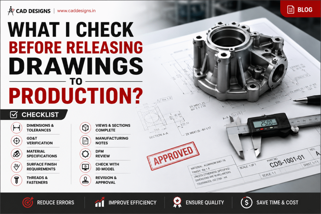
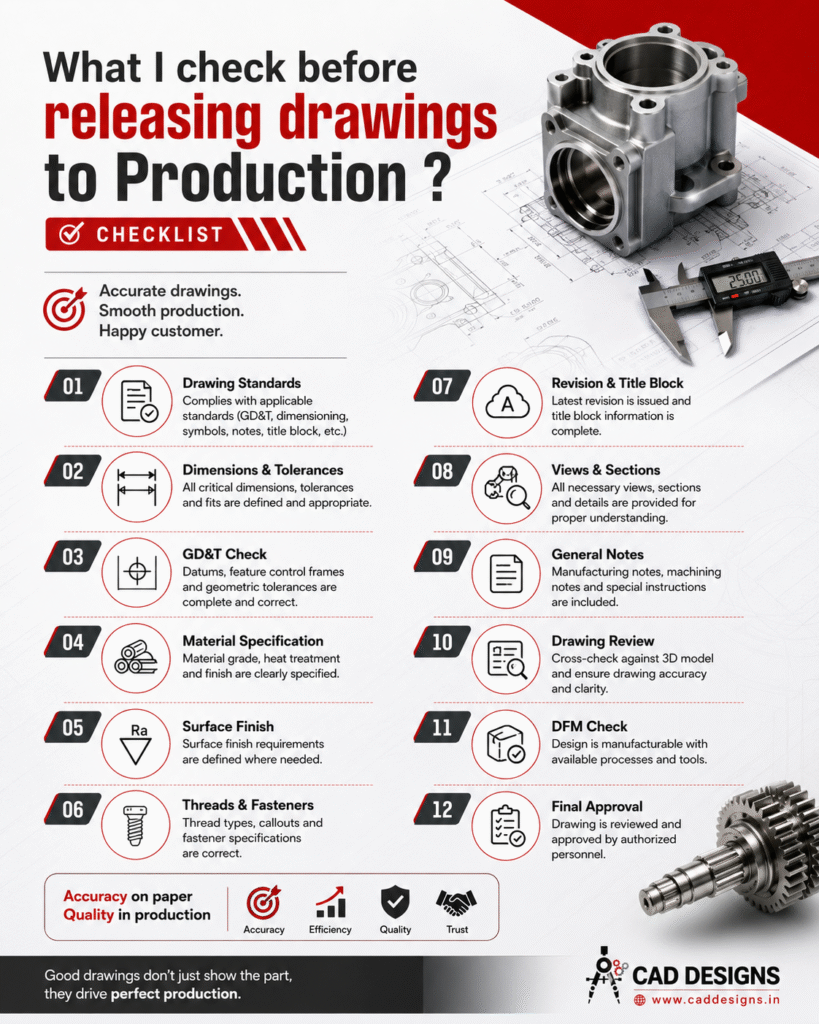
Quick Drawing Release Checklist
Before releasing any drawing, verify:
✅ Drawing standards
✅ Dimensions
✅ Tolerances
✅ GD&T
✅ Material specifications
✅ Heat treatment
✅ Surface finish
✅ Threads and fasteners
✅ Views and sections
✅ Manufacturing notes
✅ CAD model comparison
✅ DFM review
✅ Revision control
✅ Inspection requirements
✅ Final approval
Conclusion
A well-prepared engineering drawing does much more than define a part. It drives manufacturing quality, reduces production errors, minimizes rework, and improves communication between design, manufacturing, procurement, and quality teams.
Experienced engineers understand that releasing a drawing is not just an administrative task—it’s a critical responsibility.
Remember:
“Accurate drawings create quality products. Poor drawings create production problems.”
By following a structured drawing release checklist, engineers can significantly improve manufacturing efficiency, product quality, and customer satisfaction.
Regards
CAD DESIGNS